Tuesday, October 13, 2015

Quad build - Phase 6 (tuning)

A few days ago I burned through (not literary) 2 batteries to get about 26 minutes of flight. Almost all of that was tuning PIDs.

The RTL feature is still something not to be trusted so I did a bit of research. The first thing that yeilded a likely result is that the compass is being impacted by the EM fields being developed within the wires/distribution board. 

So why does this spiral? Well it seems rather simple:
Think about what happens when you put a magnet to a needle compass, what happens? The needle gets stuck in a specific orientation and thus is a compass failure. Something similar is going on with the electronic compass in that it locks up. But... the reason why it can sort of know heading is because of a faster routine that uses the accelerator to calculate heading. With the vibrations and algorithms used to smooth and sample the forces in all axis there tends to be drift of some type. This drift will cause the copter to do the circle that it doesn't think is happening. 

My APM2.8 board has the option to easily mode the compass to off-board. It requries 2 MUX solders seen from the 6 pads on the top-left of the board along with a jumper removal to disable the internal compass
Note the 2 solder pads that select MUX_SDA and MUX_SDL


And note the jumper and I2C port


After the "update" and a bit of re-tuning the quad now reliable RTL/RTH quite well without me needing to override auto-land.

A bit more tuning involved the auto-tune and some PID adjustments. In the end I did some light weight in-flight changes to PID values to create a stable flight. 

Wednesday, September 2, 2015

Quad Build - Phase 5 (First flight)

First, un-tuned flight:

Went well. After the flight I did a auto-tune with did boost the P values from 4.5 to 4.85 it does seem to be a bit more stable. This day couldn't have been much better for auto-tune, no or very little wind and clear skies make the auto-tune work for about 4 minutes.

While in the first auto-tune I apparently hit my failsafe battery limit (admittedly set too high) which took over the quad and bumped it up to about 30' and then landed. At the time I didn't know this was going on and thought I had a fly-away scenario. Luckily I had my laptop hooked up via MAVlink which showed me it was in failsafe mode which my last setting was RTL.
(RTL was set to go up about 30', go to home, then LAND)

After the next flight went well I downloaded the logs from the quads flash. I learned that for most of the time the power draw was around 118W idle. This means that each motor was running around 28W (minus electronics/esc loss). The bench tests showed that I likely needed at least 30W to maintain my almost 1.1kg quad so this is looking rather good! Based on this I should be able to loiter for around 13 minutes

Wednesday, August 26, 2015

Quad Build - Phase 4

Initial bench tests went well. I tied the quad onto a rope with a tripod to stabilize it before takeoff. The tripod was required since I opted to add the safety feature of only arm if flat.
To tie up I used the top plate and 2 PSU power wires to look over the rope and though the top plate holes. Binder clips allows me to secure the connections without trying to tie wire.

From here I was able to verify the forward, backward, and roll left/right. I did find out that I needed to reverse forward/backward on my remote which was easy via the menu.

I concluded that PID adjustments via this method may not yield desirable results due to the tension of the rope. This may not be true and maybe the adjustment would go well, just a feeling that it wouldn't.

So, getting this to hover I do put the throttle at around 45% but that doesn't mean that the T/W ratio is only 2:1. The arducopter firmware states that it automatically attempts to align hover with 50% throttle. This is an option in the control (Mission Planner) that I left on for the sake of simplicity to start. After that throttle point things should start to ramp up quickly once at full throttle, something I'm still scared about testing in an closed environment.

The next day I took this into the garage while it was empty and did a test flight there. From the start there was obvious room for improvement as the takeoff was anything but smooth. I'm thinking that there are 2 things going on for the shaky takeoff: PID tuning is not too great and vortex states. Given that this is pushing a lot of air and a garage can wrap some of that air around from floor/wall/ceiling the quad is going to create its own wash which can cause the instability. The best way to remove that variable is to take it outside!

Next step: Take outside, pray it doesn't fly off (or tether it down) and attempt APM auto-tune. The Auto-tune that APM has states it works the best when not so windy so that could be a challenge as of late. Perhaps maybe just a very large and open field is what's needed which a significant drift is ok then.

Friday, August 21, 2015

Quad build - Phase 3

Finally, my flight controller came in via China Post after a few week of waiting. The FC is Ardupilot (APM) and the kit contains
  • APM2.8 FC
  • Telemetry
  • GPS
  • volt/current meter
  • OSD


Testing motors using a low power supply. Verification of motor connections
*Pre tie-down


Final weight is around 1084g. 
Almost everything is tied down internally to make it as neat as possible. 

Next steps: Tuning and bench tests

Tuesday, August 18, 2015

Quad build - Phase 2


New motors are in and tests conducted to figure out the power-thrust ratios.

 I soldered on the ESCs to the distribution board. This is likely going to change to remove a few grams of weight from the excessive wire. I may also print something to hold the ESCs internally instead of zip-tie to the arms.

Quad mostly built and ready for tests. Here's the objective of the tests:

  • Get the motor power draws at speeds
  • Get the thrust capability at each motor draw point
  • Determine flight time
  • Determine possible flight speeds
Tools used:
  • Standard computer PSU with 12V 15A rating
  • 2 multimeters
    • One to measure the voltage from the PSU at source
      • Replace the scope meter with this if not available
    • One to measure the current
  • Scope meter
    • Measure the voltage at the distribution board (this is very important)
  • 2Kg scale

Procedure
  1. Hook up power from PSU to distribution board, use a multimeter with a 10A capability inline to get current
  2. Hook up Scope to distribution board
  3. put leg on scale
  4. Add a decent weight (1-2lb object) to on quad to keep stable and down while testing
  5. Scale should be reading 0 at this point.
  6. Hook up RX to motor over scale
  7. Power on everything
    1. Verify radio
    2. Verify that TX 100% == ESC 100% (may need to calibrate ESC)
  8. Start measuring
    1. Throttle up one notch, note volt/amp and negative weight
    2. Continue going up until 100%
Ok. Now that's done there's obvious room for improvement and changes. For example the PSUs thin wires wont be able to keep up with the draw (this is why I used 2 meters just for knowledge) 

Results:
Volt (At dist)AmpMotor PowerThrustG/W
11.60.53.486017.24137931
11.30.968.58812814.90451793
111.8518.1522812.56198347
10.63.3333.17835810.79028272
10.2548.964809.803921569
9.5764.65788.947368421
My PSU and cable arrangement started to pucker out and this was the limit. Though on these results I'd have to say the motor/rotor combo should do very well!

Next to come: Putting everything together with the FC

Monday, August 17, 2015

Quad build - Phase 1

Building a quad these days is easier than it would have been a few years ago. Almost all the components can easily be found on Amazon for a reasonable price. Sure, you can get a quad for a low price and in most cases the sum of components is greater than a RTF product, but where's the fun in that?

This blog will be about what I go through and how my build progresses
The core components for my build (excludes FC, remote, and battery)

Phase 1 - selecting all the components

Here's a general idea of the basics (I'll show what was picked for my build after)
  • Frame
  • Motor + Props
  • ESC
  • Flight Controller
  • Battery
  • RX (Reciever) and TX (Transmitter)
  • Weight (not an item, but topic)
The Frame
This is somewhat subjective and dependent on how the quad is being used. For racing, the design should be centered around a 250 and not a 450. For load/power go higher towards 450. For extreme go higher and with more arms. The size is limitless, however there's a fine balance between frame size, flight time and maneuverability. 

The Motor:
Motors range from high-speed to low speed. Each has a purpose and needs a prop that matches the motor. For example, pick a fast motor but a large prop and the motor may not have enough power to support the prop. Similarly using a 920kv motor with a 5045 will likley not leave the ground since the motor can't spin fast enough. Do some research on which matches your motor/prop and what the intent is. 
The general rule of thumb is, if you want power/lift get a combo that has a high thrust ratio. If you want flight time focus on G/W (efficiency) and keep in mind the weight. You could have the most efficient motor/prop but loading it to the max would kill battery life as well. 
At minimum:
  • Keep the thrust-to-weight no less than 1 (otherwise it will never take off)
  • Keep the weight of the motor as small as possible (helps with thrust-to-weight + flight time)
  • Match the motor to the frame size, i.e. a 450 frame is well matched with a sub 1000kv motor with 9" to 10" props. 
The ESC:
This is the easy part, pick one that matches the motor. For example, if a motor can draw a max of 18A pick an ESC with capability of no less than 20A. There's a few pits though, if you get an ESC with rating of 30A for a 18A load, nothing bad about that but the added weight could offset the benefit of life span of the ESC. Remember, just because it says 30A doesn't mean it's going to dump 30A and burn the motor. It just means that it has the capability to provide 30A.
The other thing to think about is the firmware on the ESC. Yes, firmware! Believe it or not they are micro-controller driven which accepts a PWM input which drives a 3-phase motor. The FETS (what constitutes the Amp rating) does the heavy lifting by turning on/off at specific frequencies to make the motor spin. The firmware makes a big difference in that the rate at which it does the commands to the motor can make an impact on flight stability, reaction and noise. A slow responding ESC (cheap budget ones) will work but expect to hear loud motor noises. SimonK is the current standard for ESC firmware as it has a frequency of 400+KHz vs a potential fraction of that. You can flash most ESC with SimonK because most of them are Atmega ucontroller but it does require additional tools/time. 

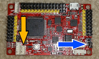
The Flight Controller:
Now why would we need one of these? Well there's a lot of math and feedback loop calculations going on to keep a quad flying correctly. Think about this: If you had to deal with 4 individual thrust generating devices to level a platform you'd likely need 2 people to manage just a stable hold. The FC takes the simple inputs of forward/back/left/right/up/down/rotate and calculates the power per motor accordingly. 
Now, beyond the basics there are a multitude of FC out there but they all run on the same idea. After doing my own research it seems that ARM based FC are going to be the new norm due to the larger ROM capacity along with compute power. Arduino is still going to exist for quite some time and is still a viable solution (maybe preferred for those who know the IDE) but will not be able to take in some more advanced features. 
Here's a small list of people/companies
  • Arduino/Atmega
    • Arducopter (ARM as well)
    • MultiWii (can support down to 328p)
  • ARM
    • OpenPilot - basic flight controller with some upgrades possible
    • Areoquad multiple sensors on board)
    • Naze32 (maybe the same as Areoquad, same sensors)
  • RaspberriPi
  • Naza (DJI controller)

Some light reading:
PID Wiki

The Battery:
Battery, like a motor, is subjective. It has some dependency on what you want to do with the quad. The main thing to keep in mind is ballance power vs weight. At some point the weight exceeds the benefit of flight time if that's the angle. Or the weight exceeds the maneuverability capability and it becomes sluggish. 
What will become evident is that quad that claim to have 20-25 minute battery life tend to be overstated. Some are true others reach that by special means (no auto-stabilization/gps/camera/load/etc). If the envionment is indoors the battery life is going to be much better than outdoors. Flying fast vs slow will also impact flight time. Extra equipment/load or electrical draw will impact flight times. 

The RX/TX:
This is probably the easiest. Get something that matches the budget and anticipated range. Also, at minimum for a intermediate quad, like this build, get a 6ch remote.
What do channels mean? Each channel is a controllable function. 
ch1: left/right
ch2: forward/bck
ch3: throttle
ch4: rudder
ch5: AUX1 (switch/multi-position switch/rotor)
ch6: AUX2 (switch/multi-position switch/rotor)
Now there are a multitude of remotes out there. Some will be hundreds and some will be $40's. Look through forums and read reviews. Pick one that will suit the needs of the craft which is typically range.

Weight:
You've heard me talk a lot about weight. This is a big component in making a quad work as it dictates many of the components and features that make up a quad. If the quad can properly manage Thrust-to-weight ratios then the rest, as they say, is history. What I mean by properly manage T/W is that not over-doing the thrust otherwise the flight time would be bad. Also not under-doing T/W which would impact load and also flight characteristics.
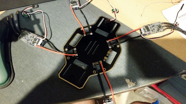
So what I purchased


  • Frame


  • Motor + Props


  • Generic 920KV motor


  • ESC


  • Flight Controller


  • Battery


  • RX (Reciever) and TX (Transmitter)


  • Weight (not an item, but topic)


  • Should be all around 1KG or slightly less. (measurement to come later) 


  • Other items


  • solder + soldering station


  • shrink wrap


  • blade balance 


  • RX to FC wires


  • motor connector 


  • wire (just to connect the battery to power distribution board) Gauge 10/12 will work well, higher gauge (numerically) means less current capability so match this to the motor draws at peak power. 


  • battery connector (match to your battery, the ones I got are T connectors. Others maybe different. 


  • Some final thoughts
    Before grabbing that soldering iron and going at it, spend 10 minutes just testing out everything. Get a 12V power supply of some type, wire it to one ESC and make sure that works and that it controls the motors properly.

    Here's a step-by-step verification

    1. 8-12V PSU (a computer PSU is ideal) with at least 5A capability
      1. We don't need as much power as the motor demand is going to be. Reason is that with no loads (props) the power requirement from the motor is significantly less than when under load for the same speed. Most actually draw less than 1A but the overhead is always a good idea for supply. 
    2. Pick one ESC, wire power to PSU
    3. Hook ESC (thin header cable) to RX ch 3 (throttle), Keep in mind the ground wire and orientation on the RX along with power and signal. We don't want to fry something here already!
    4. Power on PSU
    5. make sure RX gets power and binds to remote
    6. Power off PSU
    7. Hook a motor up to the ESC
    8. Power on PSU
    9. Give a little throttle, make sure motor works
    10. Full throttle (careful about motor shift) and make sure there are no noises that sounds like and old HDD or anything funny. 
    11. Power off PSU
    12. Repeat 2-11 until you go through all motors and compare noises/speeds/etc to others. 
      1. This identifies if any motor is going bad and needs to be replaced
    13. Make sure to Power off PSU
    14. Replace ESC with another, and continue steps 2-11 with a single motor to verify and each ESC works and gives that motor same sounds
    15. Power off everything
    16. Done
      1. Unless you're very paranoid, get the scope and look at the power signals coming out of each ESC to make sure it's stable during all power operations/loads. This could potentially solve issues later if the quad "drops out of the sky" when you do something mid-air as the ESC basically browned out the micro controller.

    I had 1 bad bearing on a motor and replaced it (Thankfully Amazon is awesome about replacements). Doing the above steps not only saved me time but also issues as I would have soldered on the connectors at that point which may have complicated the return process/acceptance.

    Next update will come once I get the new motors

    Saturday, August 6, 2011

    Ninja 250 Brake light upgrade

    So I wanted o upgrade my tail light so that inattentive drivers know I'm slowing down. The biggest problem I noticed on the Ninja 250 is that the standard light (single pod) doesn't have good contrast. Even though the bulb is powerful, I don't feel it suits safety very well.

    It was dumb luck that I discovered a perfect MR16 LED bulb on Amazon for $13.

    It's a 5W, 250lm bulb which after removing some plastic, it fits perfectly in the extra unused pods on the tail light.

    Originally I was planning on having a dimmed light because the controller inside the bulb supports some dimming. Turned out I would have needed to develop more than what I wanted to. The single LED driver wouldn't have been able to power 6 LEDs (from 2 bulbs) on the 12V bike power.
    You can see the 2 MR16 bulbs on the external pods. They fit (with removed lenses and rings) right where a bulb socket would have gone. 

    I decided to just have it completely off and then on when braking only.
    Normal operation just has the standard running light.
    With the brakes on it's a LOT better than just the center bulb only. The 2 pictures are taken a the same speed/aperture for good comparison.

    Overall I'm very happy with the upgrade and feel a bit safer. The LEDs turn on almost .25s (or more) faster than the standard bulb. The LEDs also allow me to brake flash better to warn people following too close or just when I may be stopping/slowing "unexpectedly"